


NewsDetails
How to connect a presasure sensor to an intelligent pulse controller?
author:yiheng time:2026-03-17 10:43:45 click:170
Connecting a pressure sensor to an intelligent pulse controller is a fundamental task for enabling demand-based(differential pressure)cleaning.This setup allows the controller to monitor the condition of the filter bags in real-time and initiate cleaning only when necessary,rather than on a fixed timer.While the exact procedure can vary slightly depending on the specific controller model and sensor type,the general process follows a standard industrial approach involving physical installation,electrical wiring,and controller configuration.
Step 1:Understanding the Components
Before beginning,it is important to understand the two key pieces of equipment you are working with.
The Pressure Sensor/Transmitter:This device measures the pressure and converts it into an electrical signal.For baghouse applications,it is typically a differential pressure transmitter.This means it has two ports:a high-side port(connected to the dirty air plenum)and a low-side port(connected to the clean air plenum).It measures the difference between the two,which is the pressure drop across the bags.The transmitter outputs a standard signal,most commonly a 4-20 mA analog current loop.
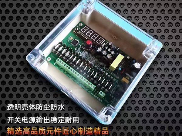
The Intelligent Pulse Controller:This is the"brain"of the cleaning system.An intelligent controller designed for on-demand cleaning will have specific input terminals designed to receive the signal from the pressure transmitter.These are often labeled as"Analog Input,""4-20 mA Input,"or"Pressure Sensor Input."
Step 2:Mechanical Installation of the Sensor
The first physical step is to install the pressure transmitter itself so it can accurately sense the pressures in the baghouse.
Locate Sensing Points:Identify suitable locations on the baghouse housing to tap into the dirty air side(inlet plenum or hopper)and the clean air side(outlet plenum or manifold).The taps should be placed in areas of representative pressure,away from direct airflows or eddies that could cause erratic readings.
Install Impulse Tubing:Connect tubing(typically 1/4-inch or 6-mm nylon or stainless steel)from the two pressure ports on the baghouse to the corresponding high and low ports on the pressure transmitter.It is crucial to keep these tubes free of kinks and to slope them downwards towards the transmitter to allow any condensate to drain away from the sensor.
Mount the Transmitter:Secure the pressure transmitter in a convenient location,often near the baghouse or inside a local control panel.It should be protected from extreme weather,vibration,and physical damage.
Step 3:Electrical Wiring
This step involves connecting the transmitter to the controller.Always ensure power is disconnected before making any electrical connections.
Identify Terminals:Refer to the wiring diagram for both the pressure transmitter and the pulse controller.Identify the transmitter's output terminals(usually labeled+and-or Out and COM)and the controller's corresponding analog input terminals.
Wire the Loop:A 4-20 mA signal is a current loop.This means the controller must provide power to the loop.Connect a two-wire shielded cable from the controller's 24 VDC power output terminal to the positive terminal of the pressure transmitter.Then,connect the negative terminal of the transmitter back to the controller's analog input terminal.This completes the loop.
Grounding:Properly ground the shield of the cable at one end only(typically at the controller end)to prevent ground loops and electrical noise interference,which can cause erratic pressure readings.
Final Connections:Double-check all wiring for secure connections and correct polarity before powering up the system.
Step 4:Configuring the Controller
With the physical connections made,the next step is to program the intelligent pulse controller to recognize and use the signal from the pressure sensor.
Access Settings:Navigate to the controller's configuration or setup menu.There will be a section for configuring the analog inputs.
Set Input Type:Tell the controller what kind of signal it is receiving.Select"4-20 mA"from the options.
Scale the Input(Set Range):This is a critical step.The controller needs to know what pressure value corresponds to the 4 mA signal and what value corresponds to the 20 mA signal.
For example,if your pressure transmitter is ranged from 0 to 10 inches of water column(in.w.c.),you would set the controller so that when it reads 4 mA,it displays"0.0"in.w.c.,and when it reads 20 mA,it displays"10.0"in.w.c.This scaling ensures the controller displays the correct pressure drop.
Set Control Parameters:Navigate to the main control settings for demand-based cleaning.Here,you will enter the target pressure set points.
High Set Point(Start):Enter the pressure drop value at which you want the cleaning sequence to begin(e.g.,5.0 in.w.c.).
Low Set Point(Stop):Enter the pressure drop value at which you want the cleaning sequence to stop(e.g.,3.5 in.w.c.).
Verify Reading:Once configured,view the live pressure reading on the controller's display.It should match a known value(e.g.,from a mechanical magnehelic gauge if one is installed).If the reading is reversed or nonsensical,check the wiring polarity or the high/low tubing connections on the transmitter.
Step 5:Testing and Calibration
After configuration,the system should be tested.Initiate a cleaning cycle manually or let the system run and observe the pressure drop.As dust loads the bags,the pressure reading should rise.When it hits the high set point,the controller should begin pulsing.You should then see the pressure drop decrease as the bags are cleaned.If the system does not respond as expected,re-check the set points,wiring,and tubing for blockages or leaks.
By following these steps,you integrate the pressure sensor into the control loop,transforming your pulse controller from a simple timer into an intelligent,responsive device that optimizes cleaning based on actual system conditions.
GB/T 7714:
SMITH J D,JONES A B.Differential Pressure Control for Pulse-Jet Baghouses:Sensor Integration and Wiring Best Practices[J].Journal of Environmental Engineering,2024,150(8):04024052.
MLA:
Smith,John D.,and Alan B.Jones."Differential Pressure Control for Pulse-Jet Baghouses:Sensor Integration and Wiring Best Practices."Journal of Environmental Engineering,vol.150,no.8,2024,p.04024052.
APA:
Smith,J.D.,&Jones,A.B.(2024).Differential pressure control for pulse-jet baghouses:Sensor integration and wiring best practices.Journal of Environmental Engineering,150(8),04024052.
 Recommended Products


 Contact Us
—— Hotline:+86 15028642444
—— Email:523474198@qq.com
—— Whatsapp:+8615028642444
—— Address:Longfengdian Village, Waliwang Town, Botou City, Hebei Province


